We create NeoPixel mild installations with Fishino and NodeMCU managed by way of Wi-Fi from a PC or Raspberry Pi utilizing a Python library.
A couple of years in the past, the American firm Adafruit Industries reworked the LED market by introducing NeoPixels, RGB LEDs that incorporate their very own controller in a single package deal.
Adafruit aimed to simplify LED administration for the Arduino group by combining the controller and RGB LED in a single unit.
Since then, NeoPixels have develop into extremely well-liked, due to the power to chain them collectively and tackle them individually, controlling every LED’s coloration and brightness. Inside every NeoPixel is an RGB SMD LED (often a 5050 sort emitting about 20 lumens) together with a WS2811 or WS2812 driver.
A microcontroller (e.g., an Arduino) sends an array of bytes with exact timing throughout all related LEDs, permitting the creation of vibrant, luminous animations.
NeoPixels can be found in varied kinds and compositions: particular person LEDs, strips, rings, arcs, and matrices.
Their widespread availability has spurred quite a few tasks showcasing their versatility, from indoor and out of doors lighting to wearable tech, LED partitions, and extra.
In lots of tasks, the microcontroller controlling NeoPixels incorporates predefined impact sequences that it loops via. Or it’s related by way of USB to a PC to obtain instructions, which makes distant set up difficult with out intensive wiring or sketch updates at any time when animations want altering.
Our Challenge
On this article, we current a system for controlling a number of NeoPixel installations round the home by way of Wi-Fi, without having to change the sketch on the microcontrollers every time. We’ll join a Fishino Guppy to a NeoPixel star and a NodeMCU to a 150-LED NeoPixel strip (each geared up with the ESP8266 chip for Wi-Fi connectivity), utilizing a Python program because the software program controller. This program, which leverages a specifically developed library, can run on both a Home windows PC or Raspberry Pi and can ship the assorted results to all related NeoPixel units over Wi-Fi.
To finish this venture, we want the next parts, obtainable from www.futurashop.it:
A 5-meter NeoPixel strip (half quantity: STRIP300LED);
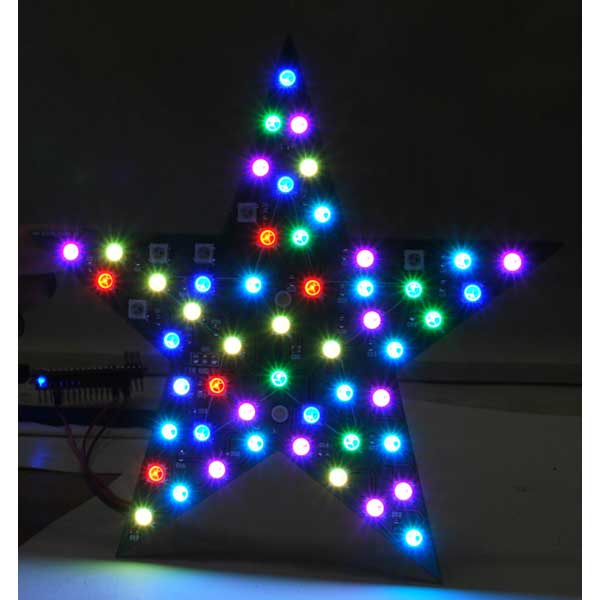
A NeoPixel star with 56 LEDs (half quantity: FT1300M);
A 5V DC energy provide with acceptable wattage (half quantity: MW05005);
A 470-ohm resistor;
Two 1,000 µF capacitors (6V or larger);
A Fishino Guppy board (half quantity: GUPPY);
A NodeMCU board (half quantity: NODEMCUESP);
A 3.3 to 5V logic stage converter (half quantity: LLCTTL);
Wiring and jumper cables;
A Raspberry Pi with a microSD card and energy provide.
When working with NeoPixels, it’s important to pick out an influence provide with the suitable score. A NeoPixel LED can draw as much as 60 milliamps when totally brilliant and white. For the 150 LEDs within the 5-meter strip, which means a present draw of 9 amps.
Different obligatory precautions embody utilizing capacitors and resistors: the capacitor is related to the ability cables with right polarity to easy the preliminary voltage spike from the ability provide that might injury the LEDs, whereas the resistor is related between the microcontroller pin and the info line (DIN) of the NeoPixel strip (a resistor is just not required for the star, as it’s already constructed into the PCB).
If you happen to use a NodeMCU, you’ll want a logic stage converter since this board operates at 3.3V logic, whereas NeoPixels require 5V (you could possibly theoretically use 3.3V if the NeoPixel energy provide is between 3.3 and three.8 volts, however we’ve a 5V energy provide).
First, obtain the venture information from GitHub (https://github.com/open-electronics/NeoPy), which embody sketches for each boards in addition to the Python library supply and pattern animations.
Put together the Arduino IDE improvement setting to program each boards. For Fishino, obtain the libraries from www.fishino.it and test that the firmware model matches the library model (go to the “Firmware Replace” web page within the “Documentation” part of the positioning for particulars).
To organize NodeMCU programming, open the IDE settings from the “File” menu, click on the proper icon of “Further URLs for Board Supervisor,” and paste this string into the window that opens: http://arduino.esp8266.com/secure/package_esp8266com_index.json.
Subsequent, set up the board by deciding on “Instruments->Board->Board Supervisor…” and trying to find “esp8266.” Set up the newest model of “esp8266 by ESP8266 Neighborhood.”
Now, underneath Instruments -> Board, you need to see “NodeMCU 1.0” within the “ESP8266 Modules” part: choose it and set the “Add velocity” to 115,200.
The ultimate setup step (wanted for each boards) is downloading the NeoPixel library from Adafruit.
Obtain the zip, unzip it into Arduino’s “libraries” folder, and restart the IDE to import the brand new library. Open the “NeoPy_Fishino” sketch (choose “Arduino Nano” within the Instruments menu), modify the MY_SSID and MY_PASS values on your Wi-Fi community and the variety of LEDs you need to hook up with the board. Go away the PORT and PIN values as they’re; uncomment and modify the IPADDR line to set a static IP, then add the sketch to Fishino.
Join the NodeMCU to the PC and open the “NeoPy_NodeMCU” sketch (choose “NodeMCU 1.0” within the Instruments menu), modify solely the values within the “SETUP” part, and depart the PORT and PIN values unchanged, then add the sketch to NodeMCU.
The system’s operation is illustrated in Fig. 1: the Python “NeoPy” library creates an object representing our NeoPixel set up, then we set the LEDs by updating solely the array throughout the object itself with the “Set()” or “SetAll()” strategies; the “Present()” methodology packages the array with the data for all LEDs and sends it by way of UDP to the desired endpoint (IP and port).
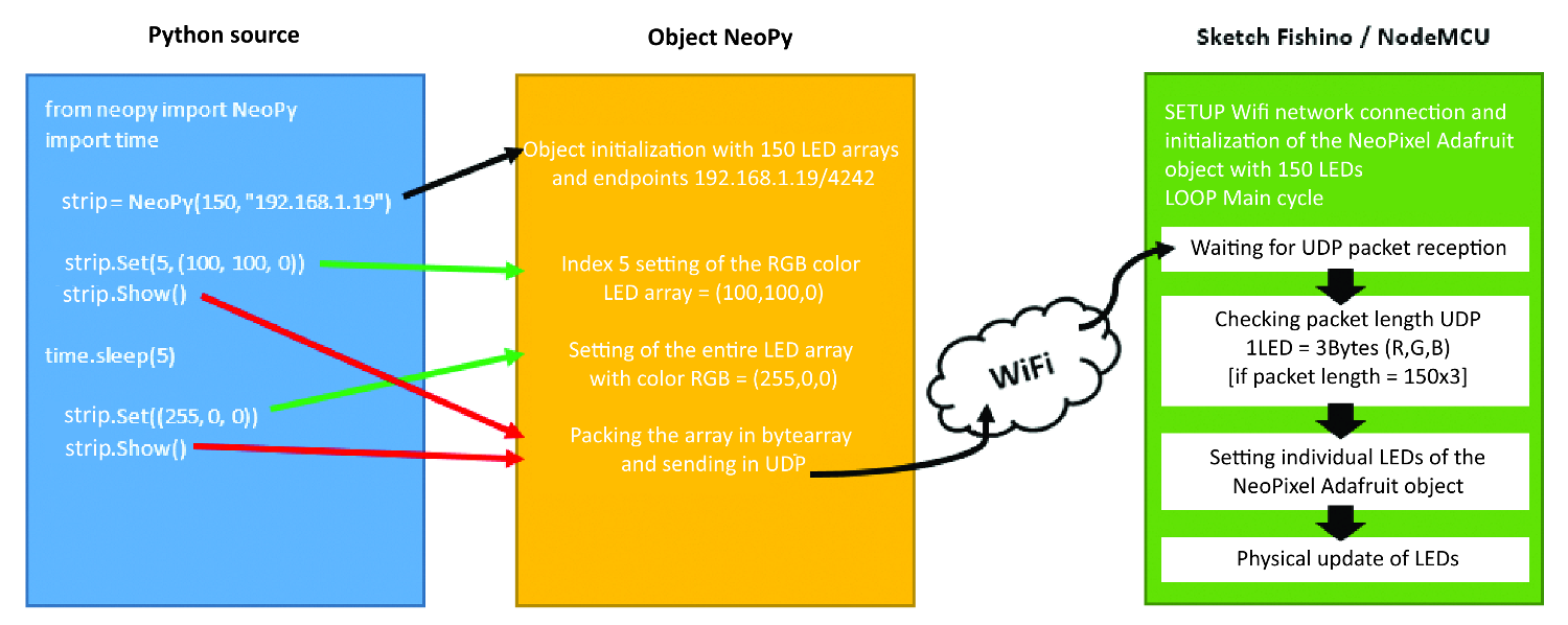
Fig. 1 NeoPy object and sketch operation
In Itemizing 1 (Fishino Guppy sketch) and Itemizing 2 (NodeMCU code), the sketches are very comparable: within the “setup” operate, the Wi-Fi connection is initialized with the beforehand configured parameters, then a UDP server is created to hear on the desired port.
Within the “loop” operate, the UDP packet is obtained, and its size is validated: an accurate packet size is 3 times the variety of specified LEDs since every LED’s coloration is represented by an RGB array of three bytes; for instance, a packet for 2 LEDs could be RGBRGB.
Itemizing 1
/* Title: NeoPy - Fishino Description: NeoPixels UDP controller Creator: Luca Bellan Model: 1.3 */ #embody#embody #embody // BEGIN SETUP #outline MY_SSID“ mio_ssid” #outline MY_PASS“ mia_password” #outline LEDS 56 //#outline IPADDR 192, 168, 1, 19 #outline GATE 192, 168, 1, 1 #outline SUB 255, 255, 255, 0 #outline PORT 4242 #outline PIN 3 // END SETUP FishinoUDP Udp; Adafruit_NeoPixel strip = Adafruit_NeoPixel(LEDS, _ PIN, NEO_GRB + NEO_KHZ800); #ifdef IPADDR IPAddress ip(IPADDR); IPAddress gateway(GATE); IPAddress subnet(SUB); #endif lengthy unsigned int packetSize; unsigned int len; int r, g, b; void setup() { whereas (!Fishino.reset()) { delay(500); } Fishino.setMode(STATION_MODE); whereas (!Fishino.start(MY_SSID, MY_PASS)) { delay(500); } #ifdef IPADDR Fishino.config(ip, gateway, subnet); #else Fishino.staStartDHCP(); #endif whereas (Fishino.standing() != STATION_GOT_IP) { delay(500); } Udp.start(PORT); strip.start(); strip.present(); } void loop() { packetSize = Udp.parsePacket(); if (packetSize == LEDS * 3) { char packetBuffer(packetSize); len = Udp.learn(packetBuffer, packetSize); if (len > 0) { packetBuffer(len) = 0; } for (int i = 0; i < LEDS * 3; i += 3) { r = (int)(byte * )(packetBuffer)(i); g = (int)(byte * )(packetBuffer)(i + 1); b = (int)(byte * )(packetBuffer)(i + 2); strip.setPixelColor(i / 3, r, g, b); } strip.present(); } }
Itemizing 2
/* Title: NeoPy - NodeMCU Description: NeoPixels UDP controller Creator: Luca Bellan Model: 1.3 */ #embody#embody #embody // BEGIN SETUP #outline MY_SSID“ mio_ssid” #outline MY_PASS“ mia_password” #outline LEDS 150 //#outline IPADDR 192, 168, 1, 32 #outline GATE 192, 168, 1, 1 #outline SUB 255, 255, 255, 0 #outline PORT 4242 #outline PIN D3 // END SETUP WiFiUDP Udp; Adafruit_NeoPixel strip = Adafruit_NeoPixel(LEDS, PIN, NEO_GRB + NEO_KHZ800); #ifdef IPADDR IPAddress ip(IPADDR); IPAddress gateway(GATE); IPAddress subnet(SUB); #endif lengthy unsigned int packetSize; unsigned int len; int r, g, b; void setup() { WiFi.mode(WIFI_STA); #ifdef IPADDR WiFi.config(ip, gateway, subnet); #endif WiFi.start(MY_SSID, MY_PASS); whereas (WiFi.standing() != WL_CONNECTED) { delay(500); } Udp.start(PORT); strip.start(); strip.present(); } void loop() { packetSize = Udp.parsePacket(); if (packetSize == LEDS * 3) { char packetBuffer(packetSize); len = Udp.learn(packetBuffer, packetSize); if (len > 0) { packetBuffer(len) = 0; } for (int i = 0; i < LEDS * 3; i += 3) { r = (int)(byte * )(packetBuffer)(i); g = (int)(byte * )(packetBuffer)(i + 1); b = (int)(byte * )(packetBuffer)(i + 2); strip.setPixelColor(i / 3, r, g, b); } strip.present(); } }
}}
The UDP packet is then unpacked, and every LED is ready; lastly, the “strip.present()” methodology updates all of the LEDs.
We selected UDP for this method as a result of it transmits packets extra rapidly than TCP, which is essential for results requiring speedy coloration adjustments. Nonetheless, UDP doesn’t deal with packet loss, particularly with gradual networks or excessive transmission speeds.
To create our results, we’ll add small delays to keep away from packet overlap on Fishino or NodeMCU. After programming each boards, join pin 3 of Fishino to the NeoPixel strip knowledge line (IN pin) by way of jumpers, together with the 470-ohm resistor as in Fig. 2.
Energy the star by way of the 5V and GND pins from the ability provide, and energy Fishino utilizing the identical 5V and GND pins. For NodeMCU, comply with Fig. 3 to attach pin D3 to the three.3V facet of the logic stage converter, then join from the 5V facet via a 470-ohm resistor to the info line of the NeoPixel strip (white wire).
Energy the converter’s low-voltage facet with the three.3V and GND pins of NodeMCU; use the 5V provide for the excessive facet, NodeMCU (VIN and GND), and the NeoPixel strip.
Energy each NeoPixel installations and make sure their Wi-Fi connection (e.g., by way of the router configuration web page or with free software program like Superior IP Scanner); obtain and set up the newest Python 3.x model in your PC.
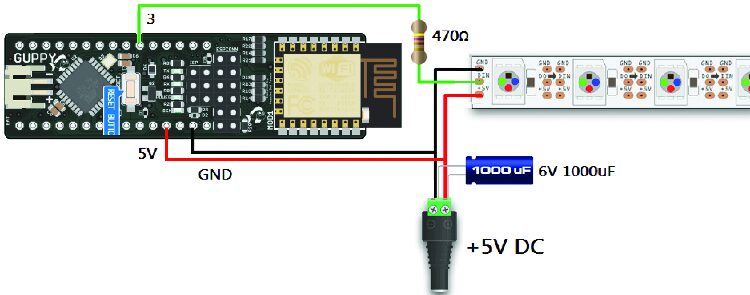
Fig. 2 Fishino Guppy and NeoPixel strip wiring diagram
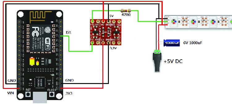
Fig. 3 NodeMCU and NeoPixel strip wiring diagram
Python Improvement
We selected Python to develop the Wi-Fi controller as a result of it’s a contemporary, versatile, intuitive, and easy-to-learn language. Moreover, it’s cross-platform, permitting our code to run on Home windows, Apple, and Linux (in our case, on Raspberry Pi).
The official web site additionally supplies an entire Python tutorial.
Open IDLE, this system simply put in, which can appear like a easy textual content editor however lets you write and run Python packages. Save the empty file in the identical folder as neopy.py.
The NeoPy library supplies the next instructions:
object.Set(N, (R, G, B)): Set LED quantity N (e.g., from 0 to 55 in our instance) to the colour represented by R, G, B (every can vary from 0 to 255); for instance, to set the fifth LED to inexperienced, use object.Set(4, (0, 255, 0)).
object.SetAll((R, G, B)): Much like the earlier command, however units all LEDs to the identical coloration (use double parentheses); for instance, to set all LEDs to blue, use object.SetAll((0, 0, 255)).
object.SetBrightness(L): Units all LEDs to brightness share L (0 to 100), defaulting to 80. For 50% brightness, use object.SetBrightness(50).
object.Wheel(V): Returns an (R, G, B) worth based mostly on the handed parameter V (starting from 0 to 255, biking via all colours); for instance, to set all LEDs to a random coloration, use object.SetAll(object.Wheel(RANDOM_NUMBER)).
object.Present(): Sends the UDP command by way of Wi-Fi to replace all LEDs bodily.
Now that we all know the instructions, let’s write a brief program:
from neopy import NeoPy
import time
stella= NeoPy(56, “192.168.1.3”)
stella.SetBrightness(30)
for i in vary(56):
  stella.Set(i, (255, 0, 0))
  stella.Present()
  time. Sleep(0.5)
The primary line imports the NeoPy library, whereas the second imports the time library, which we’ll use to time the animation. Subsequent, we create a NeoPy object named “star,” indicating 56 LEDs and IP tackle 192.168.1.3 (port 4242 is the default and will match the sketch).
We then set the general brightness to 30% and create a for loop the place, at every step, variable “i” takes values from 0 to 55. At every step, we set one LED to pink utilizing the “Set()” methodology, replace the LEDs with “Present()” and wait half a second with the “time” object.
Ensure to align the three instructions contained in the for loop with a tab, or Python will throw a compilation error. Save and press F5 to run this system: if all settings are right, the NeoPixels on the star will animate.
You possibly can instantiate as many objects as you want; as an illustration, with the next code, we instantiate each the star and the NeoPixel strip, coloring one white and the opposite pink:
from neopy import NeoPy
stella= NeoPy(56, “192.168.1.3”)
striscia= NeoPy(150, “192.168.1.19”)
stella.SetAll((255, 255, 255))
stella.Present()
striscia.SetAll((255, 0, 0))
striscia.Present()
Within the venture repository on GitHub, you’ll additionally discover the “examples_star.py” and “examples_strip.py” information, which embody examples that will help you perceive the assorted scripts for creating animations.
Now, let’s change to Raspberry Pi to run the identical Python scripts we created on the PC. Obtain a brand new Raspbian picture from the official web site, write it to the MicroSD with Win32DiskImager, insert the MicroSD into the Raspberry Pi, energy it on, and join it to the identical community as our NeoPixels.
Utilizing an SSH terminal (like Putty or MobaXTerm), hook up with Raspberry Pi (username “pi,” password “raspberry”) and navigate to the “pi” listing: cd /dwelling/pi/. Set up Git with the command (press Y and Enter when prompted): sudo apt-get set up git. Subsequent, obtain the venture information from GitHub and enter the listing with the next instructions:
git clone https://github.com/open-electronics/NeoPy cd NeoPy/
Be sure that you’re in the identical listing as “neopy.py” by typing ls -l and create a brand new file “check.py”:
nano check.py
Copy the code for the small program that activates one LED at a time on the star and shut the file by saving it with CTRL+X, then Y, and Enter.
Run this system with:
python3 check.py
The NeoPixel star will mild up simply because it did after we ran the identical program on the PC. This lets us keep away from leaving a PC on because the Wi-Fi controller for all NeoPixel installations—as a substitute, we’ll depart the rather more compact and energy-efficient Raspberry Pi working.
Think about creating a number of Python packages on our Raspberry Pi, every executing totally different results on our NeoPixel installations at varied instances of the day.
Manually launching these every time could possibly be inconvenient, so we are able to use “crontab,” a scheduler in Raspbian, to set particular instances to launch every program. The syntax could seem difficult at first, however we’ll undergo it intimately.
Sort the command:
crontab -e
The primary time, you’ll be prompted to decide on an editor to edit the schedule file; sort:
2 (Nano) and press Enter.
This opens the modifying window the place you’ll insert process strains, with every line representing a program to be executed, and containing six parameters separated by areas: MI H D MO DW COMMAND.
Let’s break down the parameters:
MI: Minutes (0-59, or * for “each minute”);
H: Hours (0-23, or * for “each hour”);
D: Day of the month (1-31, or * for “every single day”);
MO: Month (1-12, or * for “each month”);
DW: Day of the week (0-6, the place 0 is Sunday and 6 is Saturday, or * for “every single day”);
COMMAND: The command to execute (all the time specify the total path to the Python file).
Scroll to the tip of the file and enter this line:
0 * * * * python3 /dwelling/pi/NeoPy/check.py
This schedules check.py to run at minute zero, each hour, every single day, each month, every single day of the week. Save and shut the file with CTRL+X, then Y and Enter, then anticipate the subsequent hour to begin, which can set off the script, and confirm that the star lights up simply as if we launched the script manually. You possibly can program all of the scripts you need by including new strains in crontab.
Conclusions
With Wi-Fi-controlled NeoPixels and the Raspberry Pi scheduling system, you could possibly place an LED strip in a bed room to simulate dawn at a particular time as a wake-up mild or create enjoyable backyard lighting results after sundown.
Moreover, by putting LEDs in varied rooms, you could possibly have them mild up at set or random intervals to simulate your presence at dwelling. Or, join sensors to Raspberry Pi and management lighting based mostly on sensor knowledge.